Kinergetics SW800 Crossover Manual

MartinLogan Audio Owners Forum

Help Support MartinLogan Audio Owners Forum:

This site may earn a commission from merchant affiliate links, including eBay, Amazon, and others.

Lurch490

Active member
MLO Supporter
Joined
May 30, 2022
Messages
38
Reaction score
19
Location
Denver, CO
I recently found and purchased a Kinergetics SW800C crossover, but without the manual. While I didn't think to be a problem because the manual was online, the DIP switches don't match the diagram in the manual online. The online manual mentions 9 DIP switches in 3 groups of 3.

Here's the diagram:

DIP Swtiches.PNG


My SW800C has 9 DIP switches per channel:

IMG_1058.jpeg


So, the burning question is: Does anyone have the diagram that shows how to configure this version?

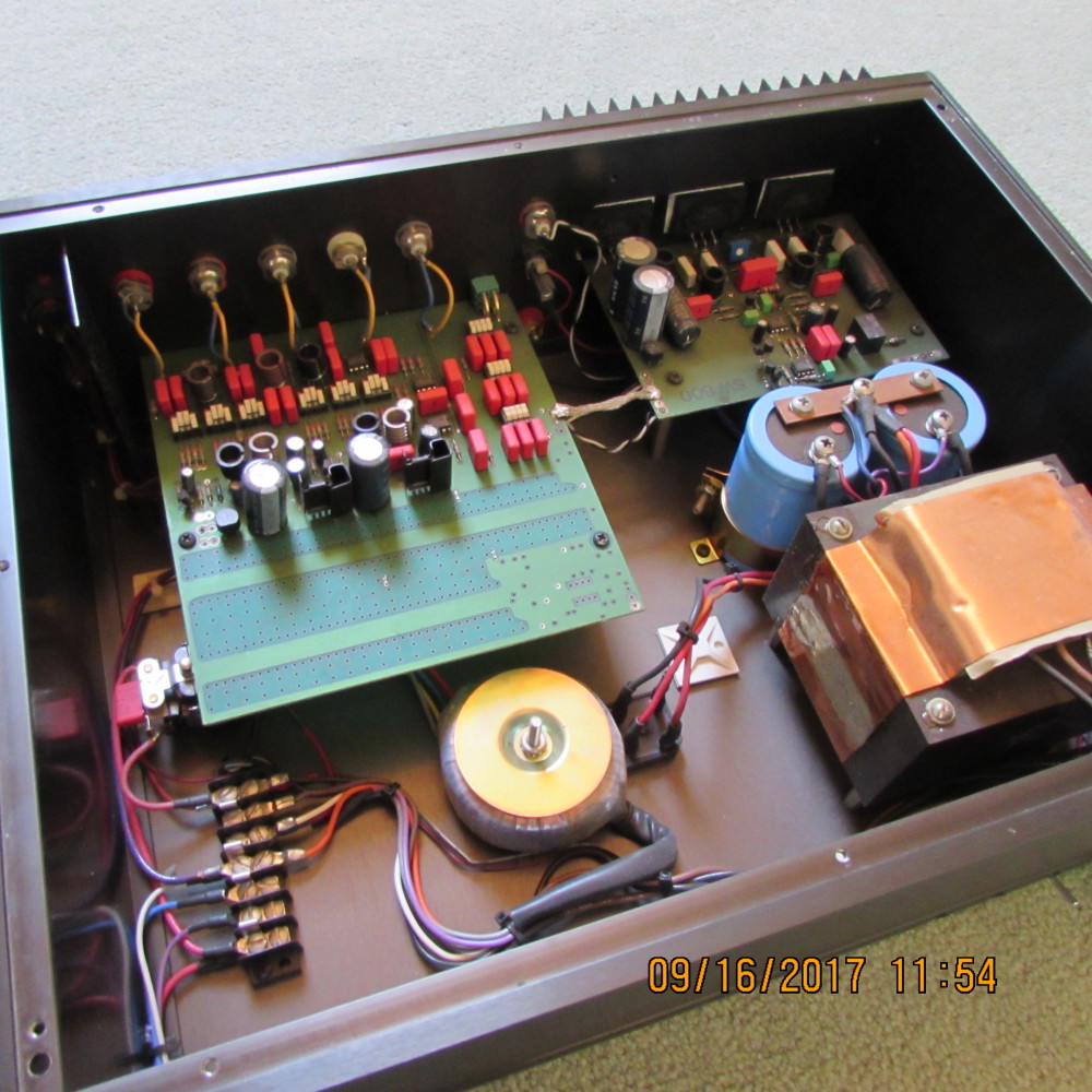
Here's what it looks like:

SW800C Front Panel.jpeg


SW800C Backside.jpeg


Thanks!
Jeff
 
I found the attached image matching the layout in your diagram. It's listed as a SW800. I'm guessing that the manual was never updated with the "C" layout.
IMG_34145B15D.JPG


I will suggest that some common sense theorizing be used and assume that the A,B,C,D,E,F,G,H,I, can be used for the Switch names on each side of the board. From what little I can see in the photo the SW# names span across both channels in one row, then again on the other row - so, sequentially the nine switches don't correlate to "each" channel but instead span across both channels. So, I would simply go from the lowest SW# on one channel, even though the numerals will jump from say, SW5 to SW11 on the channel that's on the right half of the board in your photo, and assume that SW1-5 and SW11-14 are all the equivalent to SWA-E and SWF-I.

See if this makes sense to you.

I can't find any diagram or schematic showing the layout for the SW800C.
 
Interesting. I have an 800C that looks just like the owners manual, but the face plate looks different. I am guessing that the circuit topology is the same but they changed the layout at the same time that they changed the face plate.

This is old gear and not many were produced. It would be great to replace this box with a DSP solution. I have most of their patent filings that show the nature of their FEED-FORWARD circuit, but I am not savvy enough with integrated circuits to unravel the mystery. If there are any electrical engineers that would like to collaborate on the project I’d welcome the help.
 
I recently found and purchased a Kinergetics SW800C crossover, but without the manual. While I didn't think to be a problem because the manual was online, the DIP switches don't match the diagram in the manual online. The online manual mentions 9 DIP switches in 3 groups of 3.

Here's the diagram:

My SW800C has 9 DIP switches per channel:

View attachment 24807
I just now noticed your circuit board is labeled as a SW800B.
 
I just now noticed your circuit board is labeled as a SW800B.
Wow, the board # doesn't match the # on the chassis. Possible they just took the 800B and made a few minor changes to it and didn't bother to change the label on the board?
 
Wow, the board # doesn't match the # on the chassis. Possible they just took the 800B and made a few minor changes to it and didn't bother to change the label on the board?
My guess is that it's an interim model, because the SW800C manual shows the dip switch module arrangement that doesn't match the actual product photo.

I know of other products that have had existing boards modified without a change in model number on the case. So the OP's product is a unicorn of some sort.

Either way, I can't find any earlier manuals. But I still believe that the dip switches can be set as per the 800C manual. I think they each do the same duty, whether they are named 1/2/3/4/5/11/12/13/14, or, A/B/C/D/E/F/G/H/I.
 
Another consideration is that you "found" a one-off that was put together for a demo/show or something.

Happened to me with an Earthquake subwoofer... it's a one-off made of 1" thick acrylic, with a woofer/radiator/amp combo that never really existed anywhere else...
 
See Figure 2 in the attached manual for the SW-800C crossover to determine how to set your dip switches. There are at least 2 versions of this crossover and I have 2 manuals that correspond to the versions I have owned.
 

Attachments

  • SW-800C Stereo Crossover[3].pdf
    1.6 MB · Views: 0
See Figure 2 in the attached manual for the SW-800C crossover to determine how to set your dip switches. There are at least 2 versions of this crossover and I have 2 manuals that correspond to the versions I have owned.
BINGO! This is what the OP needs! Perfect, thanks!
 
I found the attached image matching the layout in your diagram. It's listed as a SW800. I'm guessing that the manual was never updated with the "C" layout.
IMG_34145B15D.JPG


I will suggest that some common sense theorizing be used and assume that the A,B,C,D,E,F,G,H,I, can be used for the Switch names on each side of the board. From what little I can see in the photo the SW# names span across both channels in one row, then again on the other row - so, sequentially the nine switches don't correlate to "each" channel but instead span across both channels. So, I would simply go from the lowest SW# on one channel, even though the numerals will jump from say, SW5 to SW11 on the channel that's on the right half of the board in your photo, and assume that SW1-5 and SW11-14 are all the equivalent to SWA-E and SWF-I.

See if this makes sense to you.

I can't find any diagram or schematic showing the layout for the SW800C.

You are correct that the switches are numbered 1-5 then 6-10 in one row and 11-14 and 15-18 in the other. I think you're correct about them corresponding to A-I for each channel. Well done!!!!

KMan nailed it though. That's the manual I needed!!!!!!
 
Last edited:
Back
Top